

Temperature and Humidity on OLED Easy
This project uses Arduino Nano and DHT11 sensor to accurately display temperature and humidity, and is portable once configured.

Components and supplies


Apps and platforms
Project description
Breadboard (any will do, I chose a mini version because I wanted to see how small I could make it)
9v battery (any will do)
9v Battery clip (to connect the battery to the power supply module)
Power supply module (I used one that came with a generic Chinese kit, and am unable to find the exact model online. My specific model has dc power input and 5v or 3.3v output options. A similar model can be found here: $ https://www.amazon.com/MakerSpot-Breadboard-Supply-Module-Voltage/dp/B08KQ9DNQZ/ref=sr_1_1?dib=eyJ2IjoiMSJ9.tzYohfMwowguJA2LznFt7-RsGS8D3K6-e5-U9m5fIcsK8r9lUDCsTJgvlj4PDcmoQ172b0R2cl2XVFzzEibaskAgu8kfnYNya-WDTKKnY9AoclD0r5tqENUrS9A2IZ_gQXg-TTTJuj9PrIuJ19XiDpIpYI3bhzhOQDIG3Papct-sNgVtuSjqLs6jQXPcSl7FMMObCG3VPiFM0MJe8tI83Xw4IuF1LT6KPHw0qW4fE6w.MC2U7nOPfZHXMo-fhZCEHvymeSOTgXQVckOD1MkDkqo&dib_tag=se&keywords=power%2Bmb%2Bv2&sr=8-1&th=1 $ )
Arduino Nano
DHT11 temperature and humidity sensor (again mine came in a generic kit, and has 3 pins. If the front of the module is the blue plastic side, then the order of my pins when looking at the front of the module from left to right is data, power, ground.)
.96" OLED 128x64 12c (12c meaning it only requires 4 pins to be connected, the link to the exact display I used can be found here: $ https://www.amazon.com/Hosyond-Display-Self-Luminous-Compatible-Raspberry/dp/B09T6SJBV5/ref=sr_1_3?dib=eyJ2IjoiMSJ9.IJoxWF1pbbgjuFzVxunatlP9ikOM7jS1JANFUa4hSgmT6XG-Z-oyRyoDpSbkxETXN5hz99engoJNDlKFuK7CrPedw4yGElEDrN1NU1L2x9TIzbDnDUqFURp5IGb1wyXZ1zv1bnmwUjHmNchKNWOF6CakcJ1nW2JBLWCLxQg9wqouTBEp3ndKPbFKpGeFYt_-w9MKZOJZpkDTD3xO-ZtR75MUkl8o-7ADRAZHiGY4zmk.PXM9Glrqd18It9Uwyacu0tuOQAMXKpKAciVW_PBihdg&dib_tag=se&keywords=.96%22%2Boled%2B128x64&sr=8-3&th=1 $ )
11 jumper wires, male to male
NECESSARY LIBRARIES:
Adafruit GFX Library by Adafruit ( $ https://github.com/adafruit/Adafruit-GFX-Library $ )
Adafruit SSD1306 by Adafruit ( $ https://github.com/adafruit/Adafruit_SSD1306 $ )
DHT sensor library by Adafruit ( $ https://github.com/adafruit/DHT-sensor-library $ )
Adafruit Unified Sensor by Adafruit ( $ undefined $ )
* I am using the "ATmega328P (Old Bootloader)" which can be found in Tools, Processor. For whatever reason the not "Old" version doesn't work, it needs to be the "Old Bootloader"
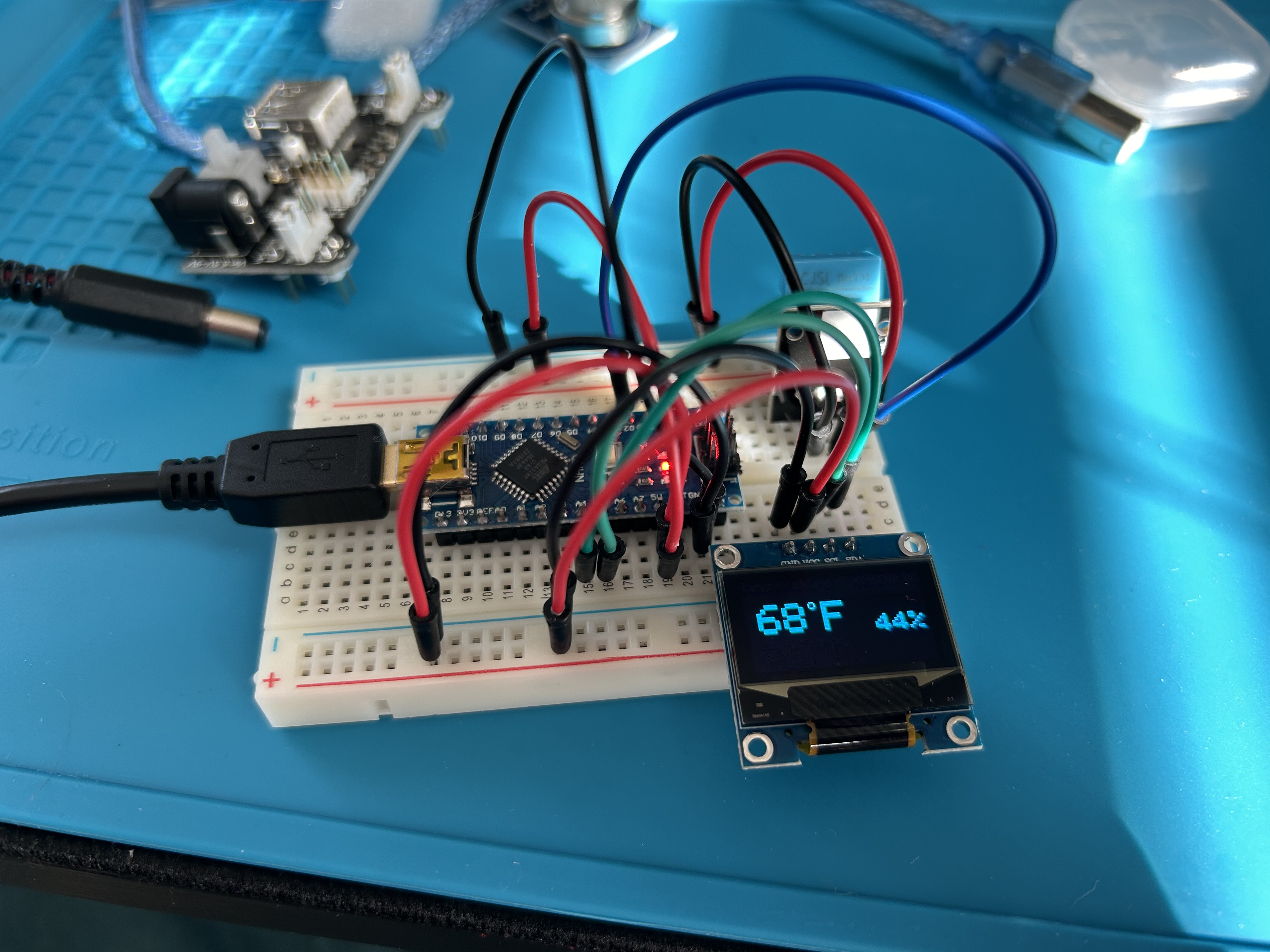
Once the code has been copied to Arduino IDE, you will need to connect the Arduino Nano to your computer to upload the code. This is easiest done by simply pulling out the power supply module and plugging into the Nano's mini USB connection. Once uploaded, the display should show temperature in F and C, as well as humidity. Once this is visible and the upload is complete, you can unplug the nano from the computer, and re-plug in the power supply module to where it was. Then, connect your battery and it will work portably.
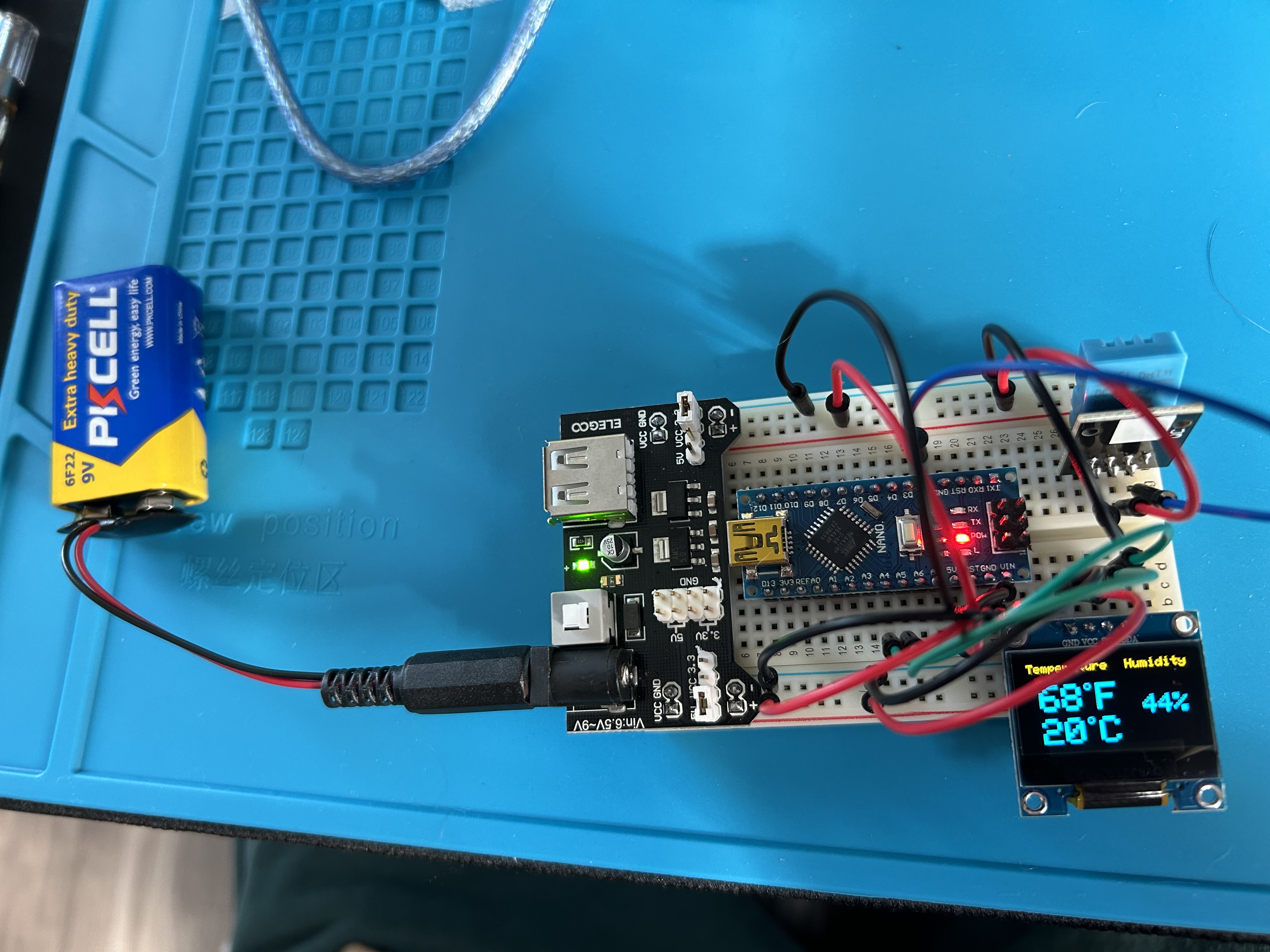
This design can be changed in a number of ways. If portability does not matter, the power supply can be removed entirely and the circuit can run via the micro USB input on the Nano. The Nano can also easily be swapped out for another board, for example you could replace the Nano with an UNO and it would work perfectly without needing to tweak the code, providing that you use the same number pins.
Also, my DHT11 pinout is listed above. If instead of accurate readings you get "NAN" on the screen, it is most likely due to your DHT11 module having a different pinout. Solutions to this are trying to find your specific models pinout online, or just trying different jumper connections. 4 pin DHT11 will also work on this circuit, but will require a slightly different connection, you would have to look up your pinout.
Regarding the schematic, it is different than the circuit shown in the pictures, but functions the same. The reason for differences is that TinkerCad, where I made the schematic, does not have many of the components I used. So, instead of the OLED in the pictures, the schematic has an LED screen (still 12C); instead of the DHT11 module I used there is a different one with a different pinout, and instead of a Nano the schematic shows an Uno. Either circuit will work, but the code would need to be tweaked and additional libraries would be required besides the ones listed above if you want to build that pictured in the schematic.
NOTES ON CODE:
My DHT11 data pin is connected to my Nano's D2 pin, or digital pin 2. This is the blue wire that can be seen in the picture above. Due to this, the code will have to be tweaked if you want to use another pin.
Code
DHT11 on OLED
cpp
Can copy and paste into Arduino IDE
Downloadable files
Schematic
Schematic slightly different from pictures


0 Reviews
Your rating